Overview
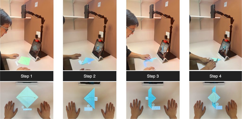
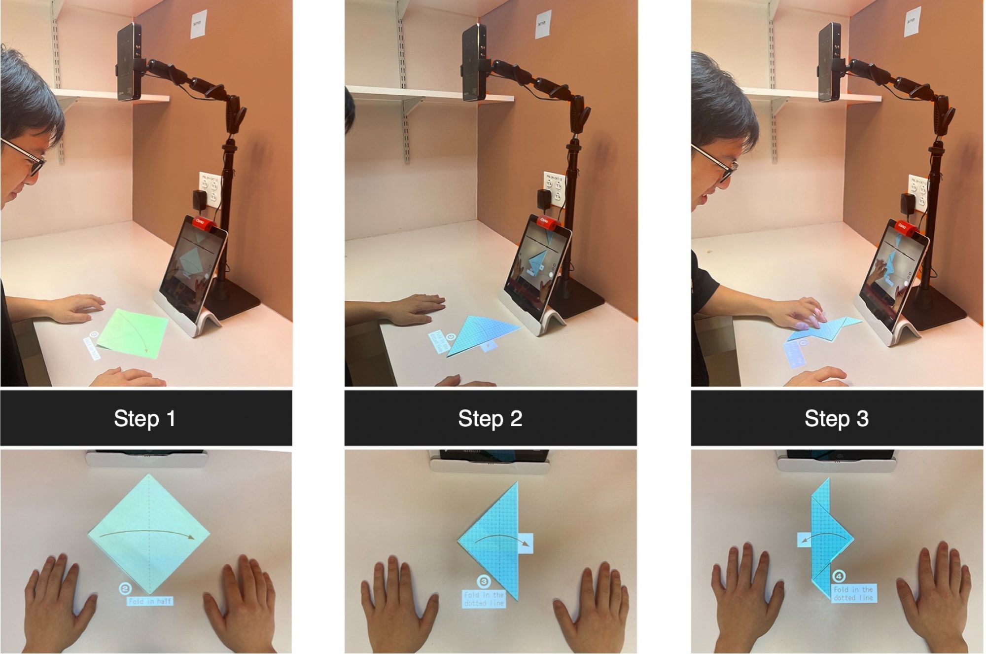
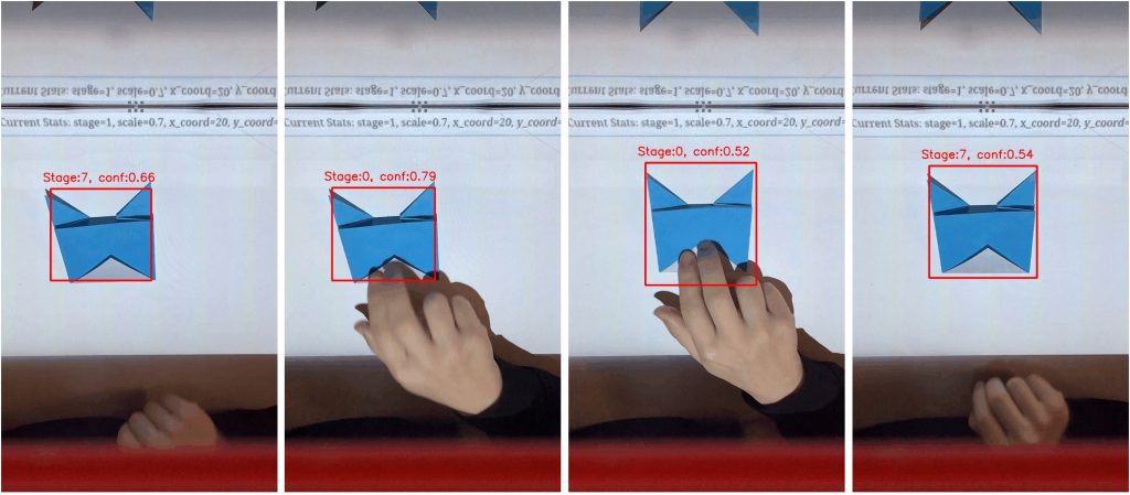
Our current set-up for this vision-based system is shown in Fig. 1 from [1], which contains the origami paper, an iPad with an OSMO stand, an OSMO mirror, and an AKASO mini projector. The OSMO mirror on the front camera helps us track the user’s activities on the table. We used a learning-based detection algorithm to detect the location and classify the current state in real time within an iOS application. Additionally, to train our detection model we collected our own dataset and designed the instructions to be projected on the paper based on the predicted location and the state of the origami. To project the instruction, we also built a website that directly receives the requests from the iOS application. The contents of the website are the current instructions being projected along with a few other instruction which could be helpful for finishing the task.
For using this application, the user has to do the simple setup as in Fig. 1 and run the iOS application on their iPad. The app will detect the paper and project the instruction on top of the paper. After completing each step, the user has to simply remove their hands from the paper for the detection algorithm to predict and project the next step. This process is repeated till they finish folding the origami.
The following sections elaborate on some critical components of our work.
Dataset
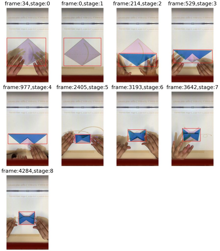
We want to detect the current state of the origami to decide which instructions will be projected. However, we also want to track the location of the paper to project the instructions such that it overlaps with the paper. We decide to use a learning-based detection model, YOLOv2 [2], to do this. We collect our own dataset for training our model for this task. We recorded 3 videos of origami being folded with the instruction being projected on the paper. We then used GroundingDINO [3] to get the ground-truth bounding boxes from the extracted frames. We made a design choice where we classified any stage where the user was occluding the paper to be state 0. This helps us to separate the transition state from each finished state that the model is trained on. We get around 1300 frames for the 9 stages.
Paper detection
To match the paper in the camera image with the instruction images, we will perform a paper detection and then estimate a homography (or transformation matrix) between the instruction and the detected shape.
We first tried to use traditional vision approaches to detect the paper. Firstly we preprocessed our images using Gaussian blurring and image dilation to improve the accuracy of the Canny edge detector. We then tried to find polygon contours from the edge map and filter out the one that belongs to the folded paper based on arc lengths and areas. Finally, using the corner points of the polygon contour and the ones from the instruction, we could optimize a 2D projective transformation.
However, the final detection accuracy of this approach was much worse compared to the data-driven YOLOv2 detector that we trained later. Therefore, we eventually decided to use this YOLOv2 detector and embed it into our iOS application to send its detection and classification result to the website back-end server, which will be discussed in the section below.
Camera and Projector Calibration
Simply performing detection in the image is not enough to localize the paper in the world coordinate (in our case, on the table). To locate users’ paper and project instruction diagrams accurately, we need to calibrate our devices in two steps. Shown in Fig. 3 are the devices being calibrated.
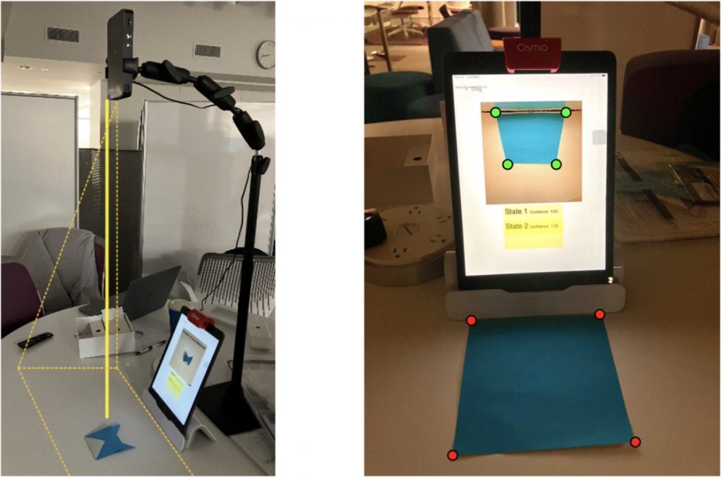
- Projector Calibration: For the mini projector, we manually adjust its stand so that it projects vertically from the top to the table, i.e. the projector aligns with the table surface’s normal direction. In practice, the stand also allows a fixed height so we can calculate a scaling factor in advance, and use this factor to determine a similar transformation for instruction images during projection. This ensures that the instructions displayed on the table are appropriately scaled and shifted based on the height of the projector from the desk.
- Camera Calibration: To address perspective distortion caused by using a mirror over the front camera of the iPad, we need to perform camera calibration. The goal is to learn a homography H to correct for the distortion caused by the mirror and determine the scaling factor and the offset for origin.
Currently, we use 4 point correspondences from the corners of a square paper to solve for H. In simple terms, for each pair of correspondences in the homogeneous coordinate,
we have the following linear constraints.

Stack the constraints for all 4 correspondences to be an 8-by-8 matrix and then use SVD as the solver for the total least squares minimization. Then H will be the right-singular vector corresponding to the smallest singular value of the final constraint matrix. In most cases where the relative position between the iPad and projector is fixed, so this homography won’t change. For dynamic and online use, one solution will be projecting some calibration images at the start of each use session, making sure they are captured by the camera, and then performing calibration.
Both of these calibrations are essential for the system to provide an accurate user experience. Camera calibration corrects the view from the iPad camera, while projector calibration ensures that instructional images are appropriately sized. These processes are crucial for maintaining the accuracy and usability of our system.
Instruction projection
In order to project the instruction to the paper, some engineering work is inevitable since there is no existing programmable API for the AKASO mini projector to control what is being projected. We explored two directions to solve this issue. The first is to install some software inside the iPad to control what is being shared (part of the iPad screen) through the HDMI cable. The other option we tried, which is more flexible but involves more engineering work, is to build a website controlled by requests sent from the iPad and let the projector simply project the website onto the paper. In the end, we decided to follow the latter approach so that we can easily and programmatically control what and where the instruction is projected on the table surface through HTTP requests and do this in real-time via server-sent events API in the front-end code.
In the back-end of the projection website, following the detection stage, we use the homography calculated from the previous section to map positions in the iPad front camera video input coordinate to the table surface coordinate, and then use the scaling factor from projector calibration to subsequently map to the projection website space. Next, we pick the next instruction image and adjust the position of instruction on the website so that the projected diagram can follows the user’s paper.
Experiments and Results
Detection Result
Our paper detector is trained on videos from different lighting and can achieve mAP@50 of 99\% on the test data. However, this number is not meant to be accurate or representative since the test data are from the same videos that the training data are extracted out of. Moreover, due to our set-up, we collect data with limited angles, background, and origami paper choices, which make the task easier at inference at the exchange of some robustness.
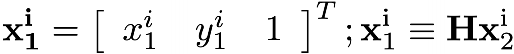
In order to properly evaluate our detection model, we also qualitatively observe its performance across different stages of the origami model, and find out that it performs quite well on most steps except for Step 3 of the model because Step 3 plus the projected website in the view of the iPad camera resembles Step 4 a lot. Overall, the predicted bounding box can follow the position of the origami paper tightly. Some examples are shown in Fig. 4.
Overall System Performance
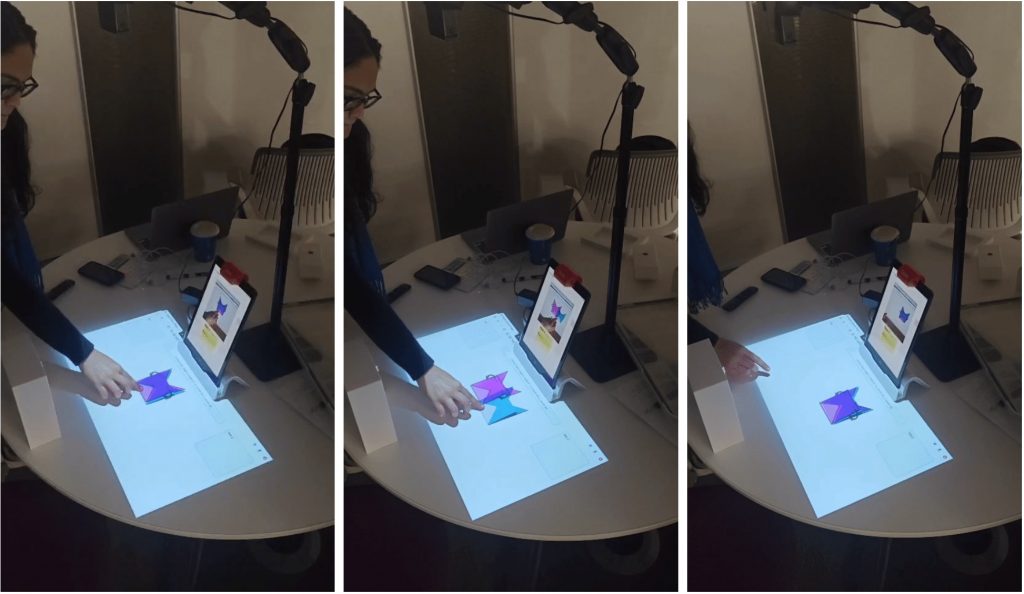
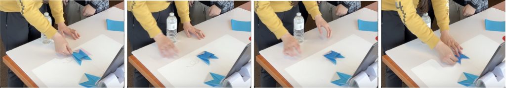
To evaluate the overall pipeline, since there is no clear method to evaluating the quality of projection quantitatively, we will simply look at the projected instruction image on the origami paper and evaluate it qualitatively based on properties like how much the counter overlaps. Two series of examples of our system are provided in Fig. 5 and Fig. 6. Based on these results, we show that our system can achieve the function of automatic paper tracking and reasonably accurate instruction projection for the purpose of origami teaching.
However, sometimes our system can still make mistakes on what and where the instruction is projected. There are lots of potential source of errors for this including the noise in the camera and projector calibration, errors in the calculation of the two coordinate exchange processes, errors in the scale and offsets for the designed instruction images, paper detector inaccuracy, difference in the set-up from time to time, invalid assumption that the projector is perpendicular to the table surface, etc.. Therefore, the natural future step for this project is to focus on and resolve each of these potential causes to improve the actual tracking performance of our system during user usage.
References
[1] Qiyu Chen et al. “Origami Sensei: Mixed Reality AI-Assistant for Creative Tasks Using Hands”. In: Companion Publication of the 2023 ACM Designing Interactive Systems Conference. DIS ’23 Companion. Pittsburgh, PA, USA: Association for Computing Machinery, 2023, pp. 147–151. ISBN: 9781450398985. DOI: 10.1145/ 3563703.3596625. URL: https://doi.org/10.1145/3563703.3596625.
[2] Joseph Redmon and Ali Farhadi. “YOLO9000: better, faster, stronger”. In: Proceedings of the IEEE conference on computer vision and pattern recognition. 2017, pp. 7263–7271.
[3] Shilong Liu et al. “Grounding dino: Marrying dino with grounded pre-training for open-set object detection”. In: arXiv preprint arXiv:2303.05499 (2023).